Replacing your Blank LCD Screen in Earlier Disklaviers

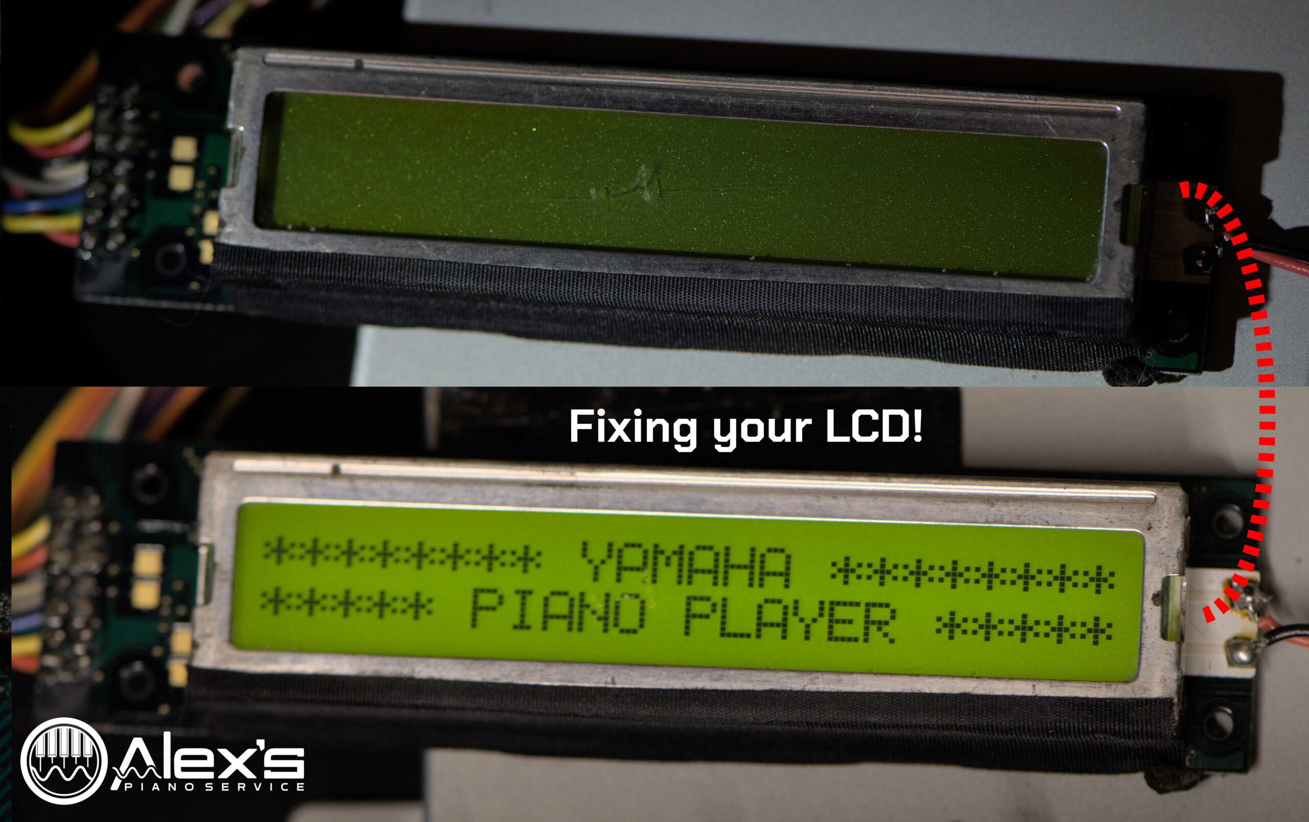
A blank LCD screen can render your Yamaha MX100II Disklavier nearly unusable. You can replace these with brand-new LCD screens, which are still available. In the MX100II and DKC5R, this is Yamaha Part #VN635201. The screens are available on Yamaha 24×7, or for a bit cheaper on SynthParts. But the issue is often fixable with a simple capacitor replacement.

Understanding the Problem: Blown Capacitors and Blank LCD Screens

The Yamaha MX100II Disklavier relies on its LCD screen for displaying vital information and controls. Over time, the capacitors on the LCD’s circuit board can degrade or fail.

The problem is typically caused by two 4.7 µF 25V capacitors mounted on the LCD screen. Electrolytic capacitors are filled with electrolytic, which can dry out or leak over time. They are a common source of failure in all electronics.

The challenge here is that these capacitors are attached to two pads on the circuit board, more typically used for surface-mount components. They’re also quite small. Together, these details make replacing them a bit trickier than your average capacitor!

The blown electrolytic capacitors on early LCD screens.
A closeup of the solder joints on an early LCD screen.

Choosing the Right Replacement: Why 35V Sprague Capacitors?

I replaced mine with 4.7 µF 35V Sprague capacitors, which will hopefully lead to longer life than the originals. While the original capacitors are rated at 25V, upgrading to 35V Sprague capacitors offers several advantages: The higher voltage rating provides better tolerance against power spikes, and Sprague capacitors are known for their reliability and long lifespan.

However, any 4.7 µF capacitor with a minimum of a 25V rating will work. Capacitors are available at minimal cost on Amazon. If you do purchase capacitors from Amazon or eBay, it’s best to purchase them at one rating: Don’t purchase a kit with many values of capacitor. These are typically of lower quality.

The Replacement Process

Removing the old capacitors is fairly straight-forward: Touch the soldering iron to each joint, and guide the legs of the old capacitors free with a pair of tweezers. Use no force. Just melt the solder, and free the legs.

Take your new capacitors and lay them on the board. Carefully trim the legs of the capacitors so that they’re short enough the capacitors fit neatly on their sides. I recently received an email sharing that, if you’re bending the capacitors after attaching them, there’s a risk of tearing the solder pads off of the board.

Position the first capacitor. Make sure its polarity is correct. Bend the legs as necessary so that they rest delicately atop the solder pads. A fine pair of tweezers will help. (Hakko makes tweezers that are exceedingly precise and easy to handle, although admittedly pricey.)

With fresh solder on the tip of your soldering iron, press the legs of the capacitors down onto the soldering pads. It’s very difficult to make a beautiful joint here, considering that these are surface-mount pads, rather than through-hole, and you’re using through-hole capacitors. But the main point is to bond them securely.

Replacement capacitors attached.  You should never take macro photography of your own solder joints.
Replacement capacitors attached. Because of the strange positioning, beauty is a real challenge here. Also, you should never take macro photography of your own solder joints.

Later Improvements to the LCD Screen

Yamaha stopped using electrolytic capacitors on these LCD screens. Newer replacements, such as the part number mentioned at the start of the article, use ceramic surface-mount capacitors. Therefore, if you opt to purchase a replacement screen, this problem will be solved forever.

Replacement LCD screens use surface mounted capacitors.

Backlight Connections

These two wires sometimes snap during the process of removing the LCD screen. This is a closeup of those joints.

The power connections for the backlight.